hdlbits_Module
Module
https://hdlbits.01xz.net/wiki/Module
By now, you're familiar with a module, which is a circuit that interacts with its outside through input and output ports. Larger, more complex circuits are built by composing bigger modules out of smaller modules and other pieces (such as assign statements and always blocks) connected together. This forms a hierarchy, as modules can contain instances of other modules.
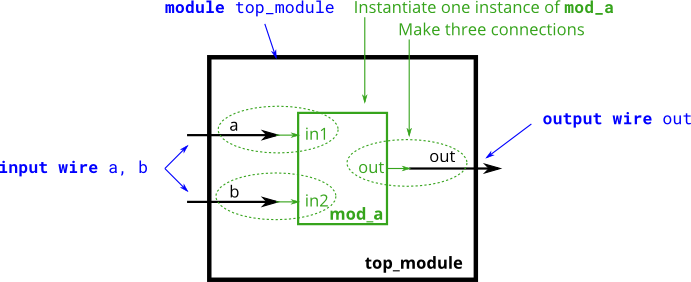
The figure below shows a very simple circuit with a sub-module. In this exercise, create one instance of module mod_a, then connect the module's three pins (in1, in2, and out) to your top-level module's three ports (wires a, b, and out). The module mod_a is provided for you — you must instantiate it.
When connecting modules, only the ports on the module are important. You do not need to know the code inside the module. The code for module mod_a looks like this:
1 | |
The hierarchy of modules is created by instantiating one module inside another, as long as all of the modules used belong to the same project (so the compiler knows where to find the module). The code for one module is not written inside another module's body (Code for different modules are not nested).
You may connect signals to the module by port name or port position. For extra practice, try both methods.

Connecting Signals to Module Ports
There are two commonly-used methods to connect a wire to a port: by position or by name. By position
The syntax to connect wires to ports by position should be familiar,
as it uses a C-like syntax. When instantiating a module, ports are
connected left to right according to the module's declaration. For
example: 1
mod_a instance1 ( wa, wb, wc );
Connecting signals to a module's ports by name allows wires to remain
correctly connected even if the port list changes. This syntax is more
verbose, however. 1
mod_a instance2 ( .out(wc), .in1(wa), .in2(wb) );
solution
1 | |